A reciprocating engine, also often known as a piston engine, is a heat engine (usually, although there are also pneumatic and hydraulic reciprocating engines) that uses one or more reciprocating pistons to convert pressure into a rotating motion. This article describes the common features of all types. The main types are: the internal combustion engine, used extensively in motor vehicles; the steam engine, the mainstay of the Industrial Revolution; and the niche application Stirling engine. Internal Combustion engines are further classified in two ways: either a spark-ignition (SI) engine, where the spark plug initiates the combustion; or a compression-ignition (CI) engine, where the air within the cylinder is compressed, thus heating it, so that the heated air ignites fuel that is injected then or earlier.
Common features in all types[edit]
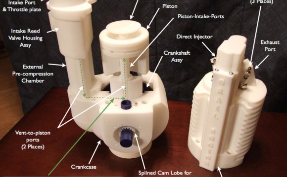
There may be one or more pistons. Each piston is inside a cylinder, into which a gas is introduced, either already under pressure (e.g. steam engine), or heated inside the cylinder either by ignition of a fuel air mixture (internal combustion engine) or by contact with a hot heat exchanger in the cylinder (Stirling engine). The hot gases expand, pushing the piston to the bottom of the cylinder. This position is also known as the Bottom Dead Center (BDC), or where the piston forms the largest volume in the cylinder. The piston is returned to the cylinder top (Top Dead Centre) (TDC) by a flywheel, the power from other pistons connected to the same shaft or (in a double acting cylinder) by the same process acting on the other side of the piston. This is where the piston forms the smallest volume in the cylinder. In most types the expanded or "exhausted" gases are removed from the cylinder by this stroke. The exception is the Stirling engine, which repeatedly heats and cools the same sealed quantity of gas. The stroke is simply the distance between the TDC and the BDC, or the greatest distance that the piston can travel in one direction.
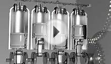
Steam piston engineA labeled schematic diagram of a typical single-cylinder, simple expansion, double-acting high pressure steam engine. Power takeoff from the engine is by way of a belt.
1 – Piston
2 – Piston rod
3 – Crosshead bearing
4 – Connecting rod
5 – Crank
– Eccentric valve motion
– Flywheel
8 – Sliding valve
– Centrifugal governor.
In most types, the linear movement of the piston is converted to a rotating movement via a connecting rod and a crankshaft or by a swashplate or other suitable mechanism. A flywheel is often used to ensure smooth rotation or to store energy to carry the engine through an un-powered part of the cycle. The more cylinders a reciprocating engine has, generally, the more vibration-free (smoothly) it can operate. The power of a reciprocating engine is proportional to the volume of the combined pistons' displacement.
A seal must be made between the sliding piston and the walls of the cylinder so that the high pressure gas above the piston does not leak past it and reduce the efficiency of the engine. This seal is usually provided by one or more piston rings. These are rings made of a hard metal, and are sprung into a circular groove in the piston head. The rings fit tightly in the groove and press against the cylinder wall to form a seal.
It is common to classify such engines by the number and alignment of cylinders and total volume of displacement of gas by the pistons moving in the cylinders usually measured in cubic centimetres (cm³ or cc) or litres (l) or (L) (US: liter). For example, for internal combustion engines, single and two-cylinder designs are common in smaller vehicles such as motorcycles, while automobiles typically have between four and eight, and locomotives, and ships may have a dozen cylinders or more. Cylinder capacities may range from 10 cm³ or less in model engines up to several thousand cubic centimetres in ships' engines.
The compression ratio affects the performance in most types of reciprocating engine. It is the ratio between the volume of the cylinder, when the piston is at the bottom of its stroke, and the volume when the piston is at the top of its stroke.
The bore/stroke ratio is the ratio of the diameter of the piston, or "bore", to the length of travel within the cylinder, or "stroke". If this is around 1 the engine is said to be "square", if it is greater than 1, i.e. the bore is larger than the stroke, it is "oversquare". If it is less than 1, i.e. the stroke is larger than the bore, it is "undersquare".
Cylinders may be aligned in line, in a V configuration, horizontally opposite each other, or radially around the crankshaft. Opposed-piston engines put two pistons working at opposite ends of the same cylinder and this has been extended into triangular arrangements such as the Napier Deltic. Some designs have set the cylinders in motion around the shaft, such as the Rotary engine.
Stirling piston engineRhombic Drive – Beta Stirling Engine Design, showing the second displacer piston (green) within the cylinder, which shunts the working gas between the hot and cold ends, but produces no power itself.
Pink – Hot cylinder wall
Dark grey – Cold cylinder wall
Green – Displacer piston
Dark blue – Power piston
Light blue – Flywheels
In steam engines and internal combustion engines, valves are required to allow the entry and exit of gasses at the correct times in the piston's cycle. These are worked by cams, eccentrics or cranks driven by the shaft of the engine. Early designs used the D slide valve but this has been largely superseded by Piston valve or Poppet valve designs. In steam engines the point in the piston cycle at which the steam inlet valve closes is called the cutoff and this can often be controlled to adjust the torque supplied by the engine and improve efficiency. In some steam engines, the action of the valves can be replaced by an oscillating cylinder.
Internal combustion engines operate through a sequence of strokes that admit and remove gases to and from the cylinder. These operations are repeated cyclically and an engine is said to be 2-stroke, 4-stroke or 6-stroke depending on the number of strokes it takes to complete a cycle.
In some steam engines, the cylinders may be of varying size with the smallest bore cylinder working the highest pressure steam. This is then fed through one or more, increasingly larger bore cylinders successively, to extract power from the steam at increasingly lower pressures. These engines are called Compound engines.
Aside from looking at the power that the engine can produce, the Mean Effective Pressure (MEP), can also be used in comparing the power output and performance of reciprocating engines of the same size. The mean effective pressure is the fictitious pressure which would produce the same amount of net work that was produced during the power stroke cycle. This is shown by:
Wnet = MEP x Piston Area x Stroke = MEP x Displacement Volume and therefore: MEP = Wnet/Displacement Volume
Whichever engine with the larger value of MEP produces more net work per cycle and performs more efficiently.
History[edit]
An early known example of rotary to reciprocating motion can be found in a number of Roman saw mills (dating to the 3rd to 6th century AD) in which a crank and connecting rod mechanism converted the rotary motion of the waterwheel into the linear movement of the saw blades.
The reciprocating engine developed in Europe during the 18th century, first as the atmospheric engine then later as the steam engine. These were followed by the Stirling engine and internal combustion engine in the 19th century. Today the most common form of reciprocating engine is the internal combustion engine running on the combustion of petrol, diesel, Liquefied petroleum gas (LPG) or compressed natural gas (CNG) and used to power motor vehicles and engine power plants.
One notable reciprocating engine from the WWII Era was the 28-cylinder, 3, 500 hp (2, 600 kW) Pratt & Whitney R-4360 "Wasp Major" radial engine. It powered the last generation of large piston-engined planes before jet engines and turboprops took over from 1944 onward. It had a total engine capacity of 71.5 L (4, 360 cu in), and a high power-to-weight ratio.
RELATED VIDEO
Share this Post
latest post
-
 Waste Management Lafayette Indiana November 14, 2023
 -
 New Zealand Waste Management November 10, 2023
 -
 Waste Management Spokane Valley Waste November 6, 2023
 -
 Waste Management Baltimore November 2, 2023
 -
 Waste Management Fort Wayne October 29, 2023
 -
 Industrial Waste Management October 25, 2023
 -
 Waste Management Macomb IL October 21, 2023
 -
 What is Waste disposal? October 17, 2023
 -
 Waste Management Pittsburgh PA October 13, 2023