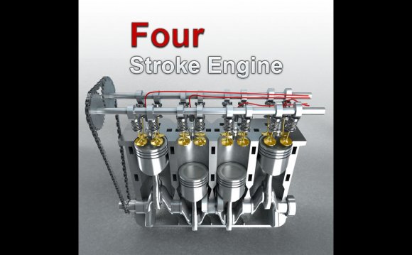
For the forty years following the first flight of the Wright brothers, airplanes used internal combustion engines to turn propellers to generate thrust. Today, most general aviation or private airplanes are still powered by propellers and internal combustion engines, much like your automobile engine. We will discuss the fundamentals of the internal combustion engine using the Wright brothers' 1903 engine, shown in the figure, as an example. The brothers' design is very simple by today's standards, so it is a good engine for students to study and learn the fundamentals of engines and their operation. On this page we present a computer drawing of the timing system of the Wright brothers' 1903 aircraft engine.
Mechanical Operation
The figure at the top shows the major components of the timing system on the Wright 1903 engine. In any internal combustion engine, fuel and oxygen are combined in a combustion process to produce the power to turn the crankshaft of the engine. To produce useful work, the combustion must take place at the end of the compression stroke of the engine cycle. Following the power stroke the exhaust valve must be opened to clear the cylinder of spent exhaust gases. The job of the timing system is to cause the various operations of the engine cycle to occur in the correct sequence at the correct time.
The timing system consists of several mechanical components. The main drive sprocket is attached to the engine crankshaft outside the crankcase on the front of the engine. The drive sprocket has six teeth that engage holes on the timing chain. The chain runs around the drive sprocket and the larger cam shaft sprocket. The arrangement is exactly like the chain on a bicycle from the pedals to the rear wheel. The large cam shaft sprocket has twelve teeth, so two revolutions of the crankshaft produce one revolution of the valve cam shaft. This is the required ratio for a four stroke engine in which the piston (attached to the crankshaft) makes two passes through the cylinder during each cycle. To keep the proper tension on the chain, there is a small adjustable tension wheel on the outside of the chain.
The timing chain turns the valve cam shaft which is located on the bottom of the engine. In the figure at the top of this page and in this computer animation, we view the engine from below.
There are four valve cams attached to the valve cam shaft. The cams rotate with the shaft and the surface of each cam rides on a rocker arm of the exhaust valve of each cylinder. Because of the design of the surface or the cam, the rocker arm is pushed down, and the valve pushed open, at specific times and for specific intervals during the shaft rotation. This motion ensures that the valve is opened only during the exhaust stroke of the cylinder. Notice in the animation that the four rocker arms move at different times. This motion supports the firing order of the cylinders.
There is a small gear located on the valve cam shaft near the front of the shaft, to the right in the figure. This gear engages another gear on the ignition cam shaft. The rotation of these ignition shaft gears cause the ignition cam shaft to rotate in an opposite direction from the valve cam shaft, but to rotate at the same speed. Located on the ignition cam shaft are four ignition cams which engage the spring switches of the electrical system. On the animation, the ignition cams and shaft are colored green. The combination of valve cams and ignition cams insure that valves are opened and closed at the correct time in the engine cycle and that ignition occurs when the valves are closed and the volume of the cylinder is the smallest.
How Does It Work?
To better understand the action of the cams, here is a diagram describing how cams work:
A cam is a metal disk for which the distance from the center of rotation of the disk to the edge surface varies as you move around the edge surface. The cam rotates on a shaft and the surface of the cam rides on an object called a follower. (For our engine, the rocker arm is the follower). As the cam rotates from position 1 to position 2, the point on the surface that touches the follower changes. Since the distance from the center of rotation varies between points on the cam surface, the follower moves. Depending on how the follower is configured, the follower can rotate, or translate, or close a switch, or perform a variety of tasks. The cam eventually rotates back to position 1 and the task is repeated. Because the actual combustion takes a finite amount of time, the firing of the ignition system usually does not occur at exactly the top of the piston motion. To allow some variation, there is a small handle on the leg of the engine which connects to the ignition shaft gear. Moving this handle, causes the gear to move slightly on the shaft so that the cam engages the switch at a slightly different time relative to the moving of the valves (and piston). This is called ignition advance and is used even on modern automobile engines. For the Wright aircraft, the advance was set before flight and could not be altered by the pilot in flight. Activities:RELATED VIDEO


