
An Introduction Fuel Systems in Internal Combustion Engines
Hello again fellows, in this post I will attempt to provide an overview of the most widely used techniques for fuel management systems in internal combustion engines. That said, you should have some very basic knowledge of this type of engines to understand this blog post. You can read my brief introduction here. Although, my posts focus mainly on gasoline engines, the below information applies to diesel ones too. So, here we are…
1) Carburetor (aka carb)
This is the “old school” type for getting the air/fuel mixture into the combustion chambers. Although it is very rarely used in modern vehicles it was the most common type used until the early 90s in both cars and bikes. Its design is straightforward as you can see in the figure below.
Now, looking from right to left in the above figure we have the following two paths for each of the mixture’s elements…
The fuel goes like this:
– The fuel pump inside the gas tank pumps gas when the starter begins
– The fuel line drives the fuel to the fuel filter
– At last, gas enters the float bowl of the carb
On the other hand, the air has an even simpler path, which is:
– If carb has air filter/cleaner, it passes through it
– Air enters the carb’s air intake
Before moving on, here is a real carb kit for V-Twin engines designed by S&S that will hopefully help you apply the above diagram information to a more realistic case.
In this picture, apart from the carb you can also see the air filter/cleaner as well as its cover, a small pipe that is used to distribute the output mixture of carb to the two cylinders of the V-Twin engine (known as intake manifold) and all the gaskets, clamps, extra fuel lines and screws required to mount this kit.
Now that you hopefully have a better picture of the whole thing, let’s jump back to the carb’s operation. In the figure I gave it is not very clear what happens to the fuel after it enters the float bowl. What it happens is that it moves to an adjustable tiny hole that let’s it flow inside the main body of the carb. Now, you can see a butterfly valve named throttle plate. This is commonly connected through a line to the accelerator pedal or lever depending on the vehicle. The more you push the accelerator, the more that valve opens delivering more air/fuel mixture to the engine.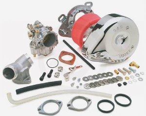 Since the delivered mixture should not be the same for all engines, carb’s provide some simple screws (look at the given picture for speed and mixture screws) that can be used to adjust the fuel jet and butterfly valve to provide the best possible mixture.
I’m fairly sure that by know you should be wondering what’s with that “choke plate” at the very entrance of air in the carb’s body. Before explaining this you should be aware that gasoline (liquid form) is not exactly flammable, its vapor is. In order to have ignition you must have gasoline that vaporizes in a good rate. You can do a simple experiment to see this working, take a small bowl filled gasoline and place a lighted match close to its vaporizing surface, it will fire up the vaporizing gas. However, if you place it fast inside the bowl, it will quench the fire of the match. That said, you can easily understand that the colder the gasoline, the lower its vaporization rate will be. For that matter, when you start your vehicle with a cold engine is called a cold start since it creates exactly this problem that requires rich mixture to overcome.
Such fuel systems (carb) have a great disadvantage when it comes to cold engine starting. Because of the high pressure that the incoming air creates, the fuel jet(s) cannot provide the appropriate amount of fuel and cylinders starve because of the lean mixture. To fix this, some manufacturers installed additional fuel jets but the most common case is the installation of a choke plate that limits the air flow and consequently lowers the pressure allowing a smooth cold start with more fuel than air (aka rich mixture). In later models, this action was performed automatically using thermal sensors that were triggering the choke plate accordingly.
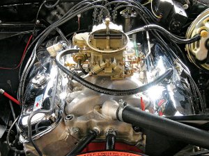
Here is a picture of a carb with the air cleaner removed on a 1968 Chevy Camaro SS:
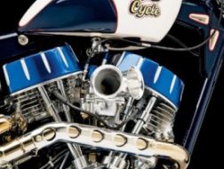
 And another one from a 2008 West Coast Choppers custom V-Twin bike with an air horn intake (no air filter/cleaner):
The main advantage of this type of fuel system is its simplicity, great torque performance and averagely easy maintenance. On the other hand, it requires small adjustments on a frequent basis, it has numerous reliability issues (it cannot perform smoothly in the whole RPM range), it has very poor fuel management efficiency and high output emission rates. However, because of its torque performance it is still used in some models either by design or as a performance tuning.
2) Mechanical Fuel Injection
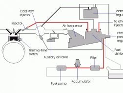
This was never truly popular compared to carburetors. It was starting becoming popular in the mid-50s mainly by Bosch. Below you can see a diagram of an Audi mechanical fuel injection system.
Basically, what we can see here is a completely different design concept. The whole system was pressure driven. The sensor plate was either providing more mixture or less depending on its incoming pressure. The air/fuel mixture was being injected directly into the combustion chambers through a series of fuel injectors, one for each cylinder.
The advantage of this system was its reliable operation in the whole RPM range and its efficient fuel management. However, its complexity made it hard to repair and maintain.
3) Central Port Injection (CPI)
This is a system which is not very popular in Europe since it was designed by General Motors and it is used mostly in GMC trucks. Here is a figure that shows the core component of CPI.
What you can see above is a system that provides fuel to an injector through a tube. The latter injector is placed directly into the intake manifold of the engine. The system is has many similarities in its operation to the mechanical fuel injection but it is electronically controlled by the vehicle’s Electronic Control Unit (ECU) to provide the best possible fuel in the whole RPM range. Later on, a multi-port system was designed by GM which is known as Central Multi-Point Fuel Injection (CMFI), in this case the injectors were spraying fuel in each intake port. The main disadvantage of CMFI was that it was spraying in all ports simultaneously. That resulted in very inefficient fuel management considering the 4-stroke engine operation. To fix this, GM later introduced Central Sequential Fuel Injection (CSFI) which, as its name implies, injects fuel sequentially in each intake port.
The advantage of this system is its smooth operation and averagely simple maintenance and repair. Nevertheless, all of these systems have major fuel leaking and fuel pressure issues. Finally, apart from the newer CSFI ones, their fuel consumption is very high compared to other fuel system technologies.
4) Continuous Fuel Injection System
RELATED VIDEO


 Engineering is the discipline, skill, and profession of acquiring and applying scientific, economic, social, and practical knowledge, in order to design and build structures, machines, devices, systems, materials and processes.


