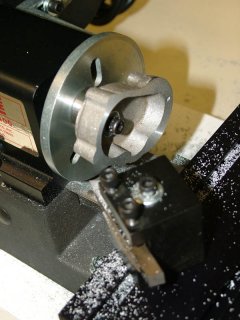
 The first cast part has the back surface flattened on the lathe. The engine will require many parts custom made from bar stock as well. We invite other machinists to become a part of this project. Participants will share in the satisfaction of seeing the finished engine run in a video on this web site. (7/25/06)
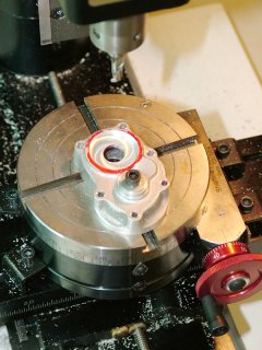
The timing cover is machined flat and the mounting holes are drilled using a rotary table
Timing cover holes are transferred to the block, drilled and tapped and then the cam positioning hole is bored to size in the cover. (8/28/06)
The crankshaft, pistons and rods are seen here in relation to the 3-view drawings thanks to very creative artwork by industrial designer Charlie Tomalesky.
Another of Charlie Tomalesky's 3D CAD drawings adds the valves and valve springs to the driveline.
As of October 4th, 2006 the block and manifolds are coming along nicely in our shop. Pam Weiss has the camshaft and timing gear well along and Joe Martin is testing a program to grind the cam lobes on a Sherline CNC milling machine.
The first cast part has the back surface flattened on the lathe. The engine will require many parts custom made from bar stock as well. We invite other machinists to become a part of this project. Participants will share in the satisfaction of seeing the finished engine run in a video on this web site. (7/25/06)
The timing cover is machined flat and the mounting holes are drilled using a rotary table
Timing cover holes are transferred to the block, drilled and tapped and then the cam positioning hole is bored to size in the cover. (8/28/06)
The crankshaft, pistons and rods are seen here in relation to the 3-view drawings thanks to very creative artwork by industrial designer Charlie Tomalesky.
Another of Charlie Tomalesky's 3D CAD drawings adds the valves and valve springs to the driveline.
As of October 4th, 2006 the block and manifolds are coming along nicely in our shop. Pam Weiss has the camshaft and timing gear well along and Joe Martin is testing a program to grind the cam lobes on a Sherline CNC milling machine.
FOLLOWUP NOTE: We modified the cam drawing to match the firing order published in the plans. It turns out the drawing was correct and the listed firing order was wrong. An old article in Model Engineer magazine by designer Edgar Westbury himself explained the error but we learned of it too late. Therefore, our firing order is actually different than what Edgar originally intended, but it runs fine.
 Charlie Tomalesky's latest drawing incorporates the camshaft into the driveline.
The drawing from 10/16/06 adds the block with a ghost view of the pistons, valves, crank and cams inside.
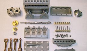
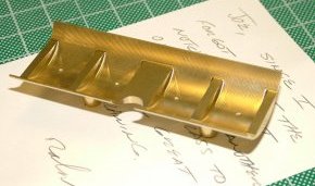
Joe's CNC cam grinder works! Pam Weiss's cam blank was ground perfectly using Joe's new CNC grinder. Shown also are the parts that have been completed as of 10/25/06, including the cast parts machined by Tom, Joe's bronze connecting rods and Pam's cam, valves, lifters and lock nuts. Note also the sandblasted aluminum engine stand Tom machined. Ralph Cooney outdid himself on this one. The oil pan was made from a solid billet of aluminum using EDM (Electrostatic Discharge Machining) to vaporize the unwanted metal. The plans called for sheet metal with machined pieces fitted to it and attached with screws. This is a much more elegant solution, but how many people do you know that have access to an EDM?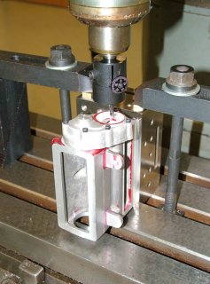 The second pan was provided by Ralph made from brass. He said the drawings by Charlie Tomalseki made it look so good in brass he felt he just had to make a second one to live up to the drawing.
The second photo shows the finished pump housing (lower left) and the brass impeller along with a couple of the fixtures Robert used to make the parts.
The four cylinder liners or sleeves were completed by Tom Boyer and Honed to exact size by Karl Rohlin. The 5th sleeve (with red mark) was the setup part. The sleeves were shipped to Australia on 11/8/06 so that Ron Chernich can make the pistons and fit the rings to the sleeves before returning them.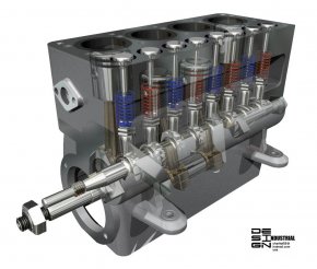 Charlie Tomaleski's digital engine is coming along nicely. Here we see the pump and ignition system added as of 11/08/06. Charlie has rendered the block as if it were made from glass so that the internal components can be seen.
Here is the block with Pam Weiss's head bolts-all 15 of them-in place. In the foreground are the two halves of the manifold which Tom is currently filing so the edges match. (11/21/06)
Joe Martin is seen sitting in front of the Sherline CNC mill setup he used to produce the spiral gears for the distributor. He cut them in brass, made a few tweaks to the program and setup and then cut the final set in steel. He's holding the just-completed set in his hand, and they came out great!
Charlie Tomaleski's digital engine is coming along nicely. Here we see the pump and ignition system added as of 11/08/06. Charlie has rendered the block as if it were made from glass so that the internal components can be seen.
Here is the block with Pam Weiss's head bolts-all 15 of them-in place. In the foreground are the two halves of the manifold which Tom is currently filing so the edges match. (11/21/06)
Joe Martin is seen sitting in front of the Sherline CNC mill setup he used to produce the spiral gears for the distributor. He cut them in brass, made a few tweaks to the program and setup and then cut the final set in steel. He's holding the just-completed set in his hand, and they came out great!
The second shot shows a close-up of the two finished gears after heat treating, which explains their dark color. The third and fourth photos show Tom Boyer lapping in the gear teeth using diamond lapping compound. The milling machine spins the vertical gear is it runs in the horizontal gear which is held in a fixture. Lapping compound is applied to the spinning gears by means of a cotton swab. The final photo shows the finished gear blanks after lapping. A US Quarter dollar coin shows their small size.
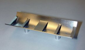
The Seal block is seen with some of the completed parts and again with the camshaft installed. (12/05/06) (L) Ron Chernich just sent this photo from Australia of his fixture and the piston rings ready for heat treating. (12/6/06)(R) Ron has finished making the pistons and rings and they are on the way to the USA for assembly. He sent along this nice shot of the pistons, rings and fixtures laid out on his drawing. (1/4/07)
Tom has finished and installed the bronze valve guides and is working on the manifold studs. A design fault in the engine that has been around since 1947 causes two of the mounting studs that occur 90° from each other to line up. It's amazing that a kit that has been out for 60 years still hasn't addressed this problem, but it's still in the drawings that way. Tom is using a tip by someone who has already built the engine to make an oversize base for two of the studs to overcome this...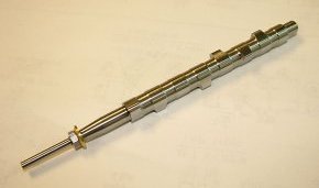
RELATED VIDEO
Share this Post
latest post
-
 Waste Management Lafayette Indiana November 14, 2023
 -
 New Zealand Waste Management November 10, 2023
 -
 Waste Management Spokane Valley Waste November 6, 2023
 -
 Waste Management Baltimore November 2, 2023
 -
 Waste Management Fort Wayne October 29, 2023
 -
 Industrial Waste Management October 25, 2023
 -
 Waste Management Macomb IL October 21, 2023
 -
 What is Waste disposal? October 17, 2023
 -
 Waste Management Pittsburgh PA October 13, 2023