D) The Air-Standard Otto Cycle (Spark-Ignition) Engine
The Air Standard Otto cycle is the ideal cycle for Spark-Ignition (SI) internal combustion engines, first proposed by Nikolaus Otto over 130 years ago, and which is currently used most motor vehicles. The following link by the presents a description of the operation including a short history of Nikolaus Otto. Once again we have excellent animations produced by presenting both the and the spark-ignition internal combustion engine engine operation
The analysis of the Otto cycle is very similar to that of the Diesel cycle which we analysed in the . We will use the ideal "air-standard" assumption in our analysis. Thus the working fluid is a fixed mass of air undergoing the complete cycle which is treated throughout as an ideal gas. All processes are ideal, combustion is replaced by heat addition to the air, and exhaust is replaced by a heat rejection process which restores the air to the initial state.
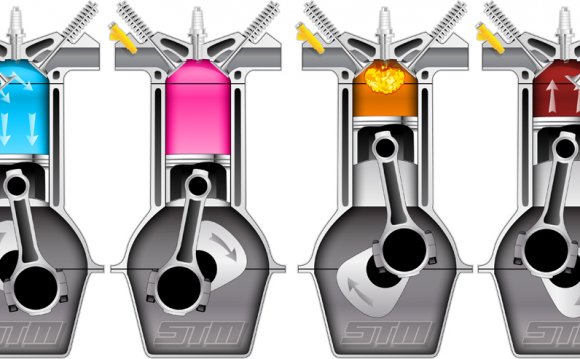
The most significant difference between the ideal Otto cycle and the ideal Diesel cycle is the method of igniting the fuel-air mixture. Recall that in the ideal Diesel cycle the extremely high compression ratio (around 18:1) allows the air to reach the ignition temperature of the fuel. The fuel is then injected such that the ignition process occurs at a constant pressure. In the ideal Otto cycle the fuel-air mixture is introduced during the induction stroke and compressed to a much lower compression ratio (around 8:1) and is then ignited by a spark. The combustion results in a sudden jump in pressure while the volume remains essentially constant. The continuation of the cycle including the expansion and exhaust processes are essentially identical to that of the ideal Diesel cycle. We find it convenient to develop the analysis approach of the ideal Otto cycle through the following solved problem:
Solved Problem 3.7 - An ideal air-standard Otto cycle engine has a compression ratio of 8. At the beginning of the compression process, the working fluid is at 100 kPa, 27°C (300 K), and 800 kJ/kg heat is supplied during the constant volume heat addition process. Neatly sketch the pressure-volume [P-v] diagram for this cycle, and using the specific heat values for air at a typical average cycle temperaure of 900K determine:
- a) the temperature and pressure of the air at the end of each process
- b) the net work output/cycle [kj/kg], and
- c) the thermal efficiency [ηth] of this engine cycle.
Solution Approach:
The first step is to draw the diagram of the complete cycle, including all the relevant information. We notice that neither volume nor mass have been provided, hence the diagram and solution will be in terms of specific quantities.
We assume that the fuel-air mixture is represented by pure air. The relevant equations of state, internal energy and adiabatic process for air follow:
We recall from the previous section that the nominal specific heat capacity values used for air at 300K are Cv = 0.717 kJ/kg.K, and k = 1.4. However they are all functions of temperature, and with the extremely high temperature range experienced in internal combustion engines one can obtain significant errors. In this problem we use a typical average cycle temperature of 900K taken from the table of .
We now go through all four processes in order to determine the temperature and pressure at the end of each process, as well as the work done and heat transferred during each process.
RELATED VIDEO


RELATED FACTS
-
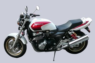 The CB1300 is a 1,284 cc (78.4 cu in) Honda motorcycle released in 1998 as a successor to the CB1000. Its engine, with only minor modifications, came straight from the Honda X4, which had been released the previous year. In 2003, the CB1300 received a slightly...
-
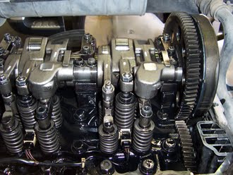 A compression release engine brake, frequently called a Jake brake or Jacobs brake, is an engine braking mechanism installed on some diesel engines. When activated, it opens exhaust valves in the cylinders after the compression cycle, releasing the compressed air...
Share this Post
latest post
-
 Waste Management Lafayette Indiana November 14, 2023
 -
 New Zealand Waste Management November 10, 2023
 -
 Waste Management Spokane Valley Waste November 6, 2023
 -
 Waste Management Baltimore November 2, 2023
 -
 Waste Management Fort Wayne October 29, 2023
 -
 Industrial Waste Management October 25, 2023
 -
 Waste Management Macomb IL October 21, 2023
 -
 What is Waste disposal? October 17, 2023
 -
 Waste Management Pittsburgh PA October 13, 2023