Please let me remind all of you-this material is copyrighted. Though partially funded by NASA, it is still a private site. Therefore, before using our materials in any form, electronic or otherwise, you need to ask permission.
There are two ways to browse the site: (1) use the search button above to find specific materials using keywords; or,
(2) go to specific headings like history, principles or careers at specific levels above and click on the button.
Teachers may go directly to the Teachers' Guide from the For Teachers button above or site browse as in (1) and (2).
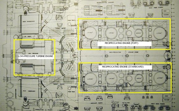
The reciprocating engine is also known as an internal-combustion engine. This name is used because the fuel mixture is burned within the engine. To understand how a reciprocating engine works, we must first study its parts and the functions they perform.
The seven major parts are:
(1) The cylinders
(2) The pistons
(3) The connecting rods
(4) The crankshaft
(5) The valves
(6) The spark plugs
(7) A valve operating mechanism (cam).
Refer to the relative location of these parts in Figure 6-2 .
Engine Operation.
The cylinder is closed on one end (the cylinder head), and the piston fits snugly in the cylinder. The piston wall is grooved to accommodate rings which fit tightly against the cylinder wall and help seal the cylinder's open end so that gases cannot escape from the combustion chamber. The combustion chamber is the area between the top of the piston and the head of the cylinder when the piston is at its uppermost point of travel.
The up-and-down movement of the piston is converted to rotary motion to turn the propeller by the connecting rod and the crankshaft, just as in most automobiles. Note the crankshaft, connecting rod, and piston arrangement in Figure 6- and imagine how the movement of the piston is converted to the rotary motion of the crankshaft. Note particularly how the connecting rod is joined to the crankshaft in an offset manner.
The valves at the top of the cylinder open and close to let in a mixture of fuel and air and to let out, or exhaust, burned gases from the combustion chamber. The opening and closing of a valve are done by a cam geared to the crankshaft. This gearing arrangement ensures that the two valves open and close at the proper times.
Now let's consider the movement of the piston (four strokes) and the five events of a cycle (see figure 6-3 ).
To see the animation 6-3 press
1. The Intake Stroke
The cycle begins with the piston at top center; as the crankshaft pulls the piston downward, a partial vacuum is created in the cylinder chamber. The cam arrangement has opened the intake valve, and the vacuum causes a mixture of fuel and air to be drawn into the cylinder.
2. & 3. Compression and Ignition Stroke
As the crankshaft drives the piston upward in the cylinder, the fuel and air mixture is compressed. The intake valve has closed, of course, as this upward stroke begins. As the compression stroke is completed and just before the piston reaches its top position, the compressed mixture is ignited by the spark plug.
4. Power Stroke
The very hot gases expand with tremendous force, driving the piston down and turning the crankshaft. The valves are closed during this stroke also.
5. Exhaust Stroke
On the second upward (or outward, according to the direction the unit is pointed) stroke, the exhaust valve is opened and the burned gases are forced out by the piston.
At the moment the piston completes the exhaust stroke, the cycle is started again by the intake stroke. Each piston within the engine must make four strokes to complete one cycle, and this complete cycle occurs hundreds of times per minute as the engine runs.
The overall principles of reciprocating-engine operation are easy to understand if you remember what happens with each stroke that the piston makes. For this reason, you may find the chart in Table 6-3 helpful.
| Table 6-3 | ||
| Direction of Movement | Event (what happens) | |
| 1. | Inward (Down) | Intake |
| 2. | Outward (Up) | Compression and Ignition |
| 3. | Power | |
| 4. | ||
RELATED VIDEO


Share this Post
latest post
-
 Waste Management Lafayette Indiana November 14, 2023
 -
 New Zealand Waste Management November 10, 2023
 -
 Waste Management Spokane Valley Waste November 6, 2023
 -
 Waste Management Baltimore November 2, 2023
 -
 Waste Management Fort Wayne October 29, 2023
 -
 Industrial Waste Management October 25, 2023
 -
 Waste Management Macomb IL October 21, 2023
 -
 What is Waste disposal? October 17, 2023
 -
 Waste Management Pittsburgh PA October 13, 2023