INTERNAL COMBUSTION ENGINE.
mvamdm Hudol 5 Diesel,
ATTO
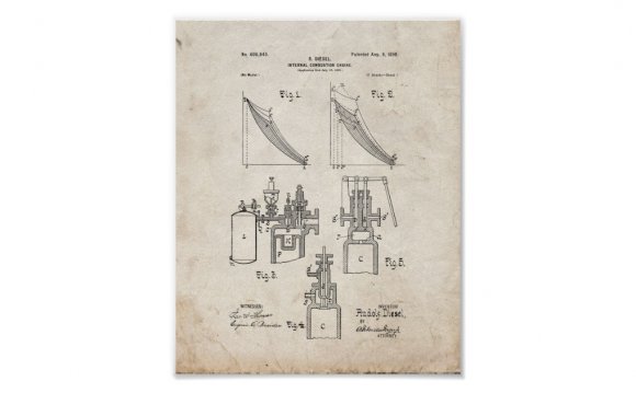
No. 608, 845. PatentedAug. 9, I898.
R. DIESEL. INTERNAL COMBUSTION ENGINE.
UNITED. STATES RUDOLF DIESEL, OF BERLIN,
PATENT OFFICE.
GERMANY, ASSIGNOR, BY MESNE ASSIGN- YORK.
INTERNAL-COMBUSTION, ENGINE.
SPECIFICATION forming art of'iLetters Patent No. 608, 845, dated August-9, 1898. Applicatio med July 15, 1895. Serial No. 656, 059. (No model.) Patented iirSp'sin December 3, 1894, No. 16, 654; in France December 10, 1894, No. 243, 531; in Belgium December 10, 18 94,
Nos. 10, 134 and 10, 135; in GermanyMarch 30, 1895, No. 86, 633; in Hungary November 23, 1895, No. 4, 639, and v Kai-ch 20, 1897, 11'0. 7, 876; in Austria'January 18, 1896, No. 46/203, and May 22, 1896, No. 46/2, 038, and in Denmark February 12, 1896, 1l'o. 393- To all whom it may concern:
Be it known that I, RUDOLF DIESEL, a sub.- ject of the King of Bavaria, and a resident of Berlin, in the Kingdom of Prussia, Germany, have invented certain new and useful Improvements in Internal-Combustion Engines,
in England, No. 4, 243. dated February 27,
1895; in Switzerland, Nos.'10, 134 and 10, 135, dated March 5, 1895; in'Luxemburg, No. 2, 192, dated December 10, 1894, and Patent of Addition No. 2, 265, dated March 22, 1895; in Denmark, No. 393, 'dated February 12, 1896; in Austria, No. 4 203, dated January 18, 1896, and -No. 46;2, 038, dated May22, 1896; in Hungary, No. 4, 539, dated November 23, 1895, and No. 7, 876, dated March 20, 1897; in Italy, LXXV, 132, dated February 21, 1895, and in Spain, No. 16, 654, dated December 3, 1894, and Patent of Addition N 0. 17, 085, dated March 4, 1895, ) of which the following is a specification.
My invention has reference to improvements in apparatus for regulating the fuelsupply'in slow-combustion motors, and inparticular to internal-combustion engines adapted for carrying outthe process described in my prior patent, No. 542, 846, dated July 16, 1895, which process consists in first compressing air or a mixture of air and neutral gas or vapor to a degree producing a temperature above the igniting-point of the fuel to be consumed, then gradually introducing the fuel for combustion into the compressed air while expanding against resistance sufliciently to prevent an essential increase of temperature and pressure, then discontinuing the supplyof fuel and further expanding without transfer of heat.
. In ordinary combustiomengines the regulation ofwork done was performed either the accompanying drawings, in which- Figures 1 and 2 are diagrams illustrating the cycle of operation." Fig. 3 is a vertical section of anengine, illustrating one form of fuel-teed, part being broken away. Figs. 4 and 5 are similar views illustrating modified forms for the feed. Fig. dis a sectional elevation illustrating another modified form for the same. Fig; 7 shows sectional views of detail parts. Figs; 8, 9, and 10 illustrate in sectional elevation the arrangement of the mechanism for operating the valve. Figs. 11,
Referring now to Fig. 1 of the drawings, which illustrates a theoretical indicator-diagram of the engine, the curve 2 3 corresponds to the period of admission and consumption of fuel, the fuel being injected under a pressure greater than the pressure 0 2 at the point of highest compression.
By varying the excess of pressure under which fuel is injected and in the meantime the length or duration of admission of fuel the combustion-curve 2 3, Fig. 1, is changed both in its form or position, as in its length 2 3, 2' 3 &c., thusproducing diagrams, such as-l 2 3 4 or 1 2 3 4', &c. In all the diagrams shown in Fig. 1 the fuel is admitted at the point 2 of highest compression. In Fig. 2 the beginning of admission is variable, as will be hereinafter explained.
Referring now to Fig. 3 for a description of an apparatus for carrying out the-regulation of the supply of fuel, the letter C designates a cylinder provided with a piston P and with an air-valve V. D is a nozzle for regulating thesupply of fuel, by meanspi'l l ichtheperiods of admission and cut-off, and consequently the length of the curve 2 3 or 2 3', &c., are determined with the use of a needlevalve n, actuated by anywell-known mechanism. 'Pulverulent solid fuel is contained, in a hopper T; provided with a rotary dis-' -tributing-valve r. L is a reservoir'which is supplied with suppressed gas through a pipe m. v.Thje gasmay be air, a combustible gas,
' or a: mixture of combustible gas and air.
i may in the usual manner regulate the supply.
The air or gas or the mixture of the same is held under a pressurefby means of a pump or other well-knownmeans) in excess-of the highest pressur in'the cylinder 0. Said rescrvoir L. is connected with the cylinder 0 by apipe S and with the hopper T bya suitable branch pipe in communication with the pipe' S.
When the valve n. is lifted to'o pen the noz zle D, the excess of pressure in the reservoir L causes the gas toflow through the pipes and the nozzle D into the cylinder C, carrying with it the pulverulent fuel discharged by the turning of the valve 'r. In this manner anlintimate mixture of gas'and fuel is obtained and injected into the cylinder and rapid and complete combustion is insured.
If the pressure in the reservoir L were fixed andeonstant, the same combustion-curve 2 3 would always result for a predetermined and fixed admission and cut-off and a predetermined or fixed highest compression in the cylinder 0; but if .under these conditions of admission and cut-off the curve of combustion is to be altered or varied then the pres:
sure :in the reservoir L must be changed. This change is elfected by means of the pressure-regulating valve R, Fig.3, the weight];
of which can be shifted by means of thefrbd valve for regulating the pressure in the res:
'ervoir L may of course be of any other construction which will answer the purpose and through the pipe m. The pressure regulation. can also be applied, as desired, to the pump feeding the tube m. This latter method would be adopted shouldfluid fuel be exclusively used, in which case the reservoir L would act as'the pressure vessel of the pump. The fuel-supply apparatus might be placed directly on the reservoir L, as the motion of the gas therein would keep the dust in sus- 1 3' 4', 3 4 &c. V effected by opening the f uel-valve a not when pension. The hopper T might also'contaiu fluid fuel.
The mixture of fuel and gas may take place inthe interior of-the cylinder or a prolongation thereof, as shown in Fig. 4. ;In this case the reservoir L contains pure compressed air, and in addition to thenozzle D for pulverulent fuel 'I provide a nozzle (Z for liquid or gaseous fuel for the purpose of intensifying combustion. In this instance the nozzle dis arranged concentric with the nozzle D, the liquid orgaseous fuel being supplied to said nozzle (1 through the lateral pipe S, while the air for combustion and the solid fuel are supplied to the nozzle D through the pipe S, leadingfrom the reservoir.
RELATED VIDEO


Share this Post
latest post
-
 Waste Management Lafayette Indiana November 14, 2023
 -
 New Zealand Waste Management November 10, 2023
 -
 Waste Management Spokane Valley Waste November 6, 2023
 -
 Waste Management Baltimore November 2, 2023
 -
 Waste Management Fort Wayne October 29, 2023
 -
 Industrial Waste Management October 25, 2023
 -
 Waste Management Macomb IL October 21, 2023
 -
 What is Waste disposal? October 17, 2023
 -
 Waste Management Pittsburgh PA October 13, 2023